Independent project · Summer 2026–present
Robotic Arm Carrier PCB
I’m independently developing a carrier PCB for a six-axis robotic arm intended to automate material feeding, build-plate handling, and finished-part removal in a 3D-printing workflow.
Schematic design, component selection, and PCB layout
First revision · In development
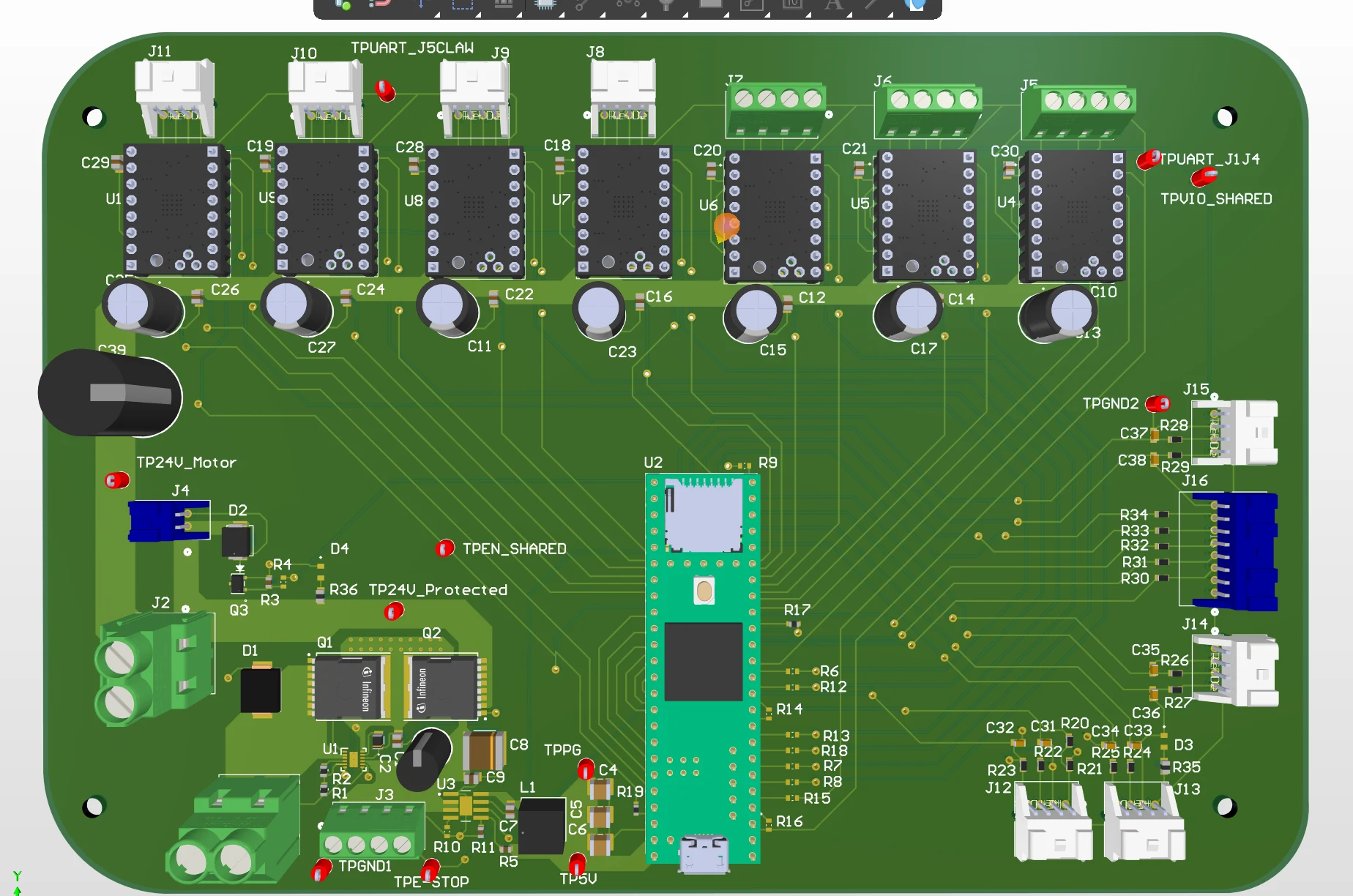 Drag to rotate · Scroll or pinch to zoom
Bringing the system onto one board
I designed the schematic and PCB layout around the specified Teensy controller and motor-driver modules, bringing power distribution, control signals, and peripheral connections onto one board.
The design provides seven motor-driver channels for six joints and a claw, five expansion connectors for signal and sensing connections, and connections for a relay, fan, and safety button.
7 motor-driver channels · 5 expansion connectors
Connections and expansion
J12–J16 provide five expansion connectors, including I²C, SPI, and auxiliary signals. The board also includes power-input protection and emergency-stop sensing.
Choosing connectors for a prototype
Connector selection balanced electrical ratings, footprint, and cost. I chose JST connectors for compact, economical signal connections and screw terminals for accessible prototype wiring.
The first layout made the packaging tradeoff visible: connectors arranged around the perimeter consume valuable board-edge space.
A smaller footprint through top-entry connectors
My main focus for the next revision is changing suitable connectors from right-angle entry to vertical, top-entry connections. Cables would plug in from above the board rather than horizontally from its edge.
This could free the layout from placing so many connectors along the perimeter, allowing a tighter component arrangement. I will also need to account for connector height, cable clearance, and access during assembly.
Components on both sides and a four-layer stackup remain secondary options. The revised layout is still being developed; a size reduction has not yet been measured.
Change connector orientation first; assess the resulting footprint and cable clearance before fabrication.